
Automotive Electronics Manufacturing: Meeting AEC-Q Standards for Reliability


Introduction / Industry Overview

Automotive electronics has undergone a structural transformation. Where electronics once accounted for roughly 15% of total vehicle cost, that figure has now exceeded 40% in premium electric vehicles (IEA, 2026), driven by the proliferation of advanced driver-assistance systems (ADAS), battery management systems (BMS), and domain-controller architectures. The global automotive electronics market was valued at approximately USD 280 billion in 2025 and is projected to reach USD 460 billion by 2030, growing at a CAGR of 10.4% (MarketsandMarkets, 2025).

Unlike consumer electronics, where a two-to-five-year design life is acceptable, automotive PCBs must endure 10–15 years and 200,000+ miles of service across extreme thermal cycling (−40°C to +150°C), continuous vibration (10–2000 Hz at up to 20 G), humidity, salt-spray exposure, and transient voltage spikes. A single field failure in a safety-critical system—braking, steering, or airbag deployment—can have catastrophic consequences. This reality has produced one of the most stringent standard matrices in electronic manufacturing: the AEC-Q series for component qualification, ISO 26262 for functional safety, ISO 16750 for environmental reliability, IPC Class 3 for workmanship, and IATF 16949 for quality management.

This article dissects the core technical requirements, application scenarios, and future trajectory of automotive electronics PCB design, with a focus on how the AEC-Q and ISO 26262 frameworks shape every decision from material selection to manufacturing process control.


Core Technology Analysis
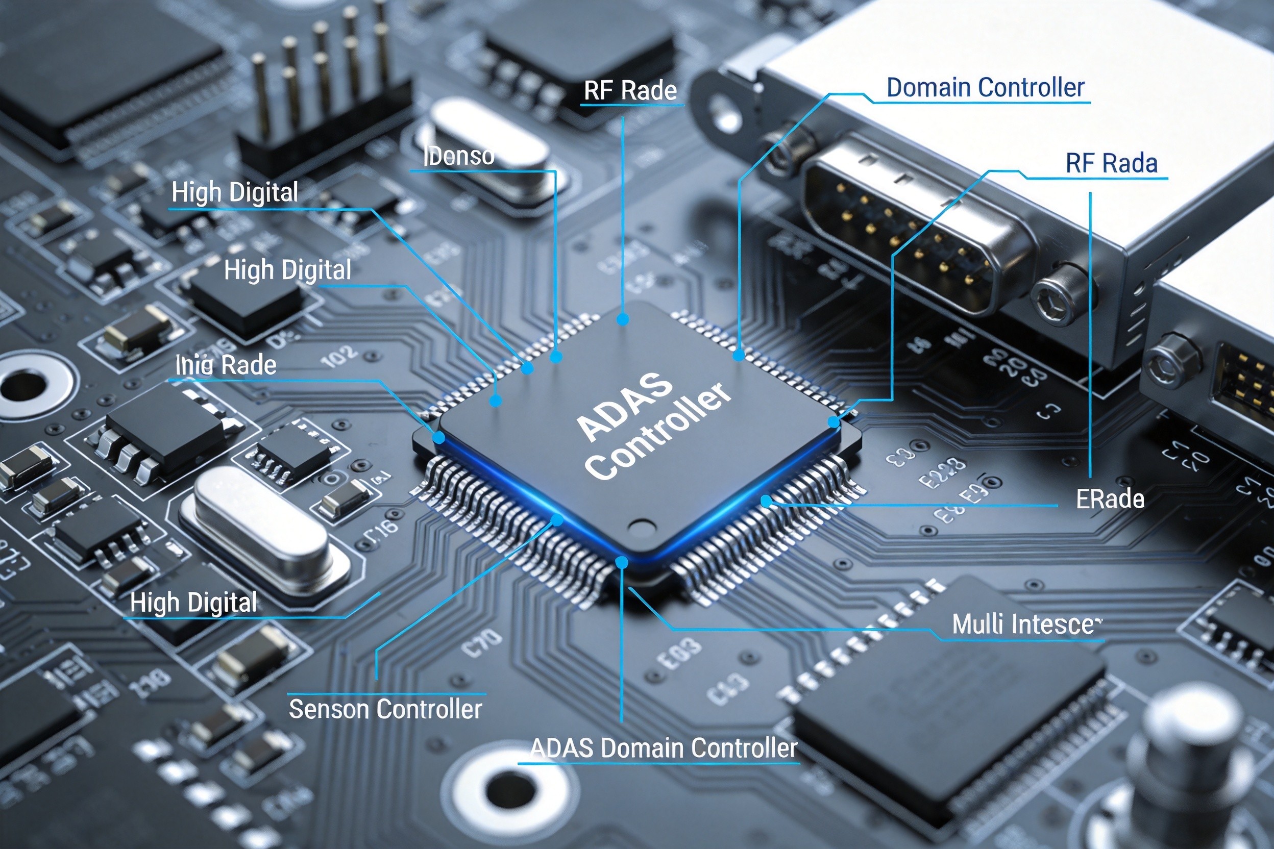
ADAS domain controller PCB with multi-sensor fusion architecture and RF radar interfaces

The AEC-Q Standard Matrix: Qualification from Component to Board Level

The Automotive Electronics Council (AEC) has established a family of stress-test qualification standards that form the non-negotiable baseline for any component entering the automotive supply chain:

Standard Scope Key Test Conditions
AEC-Q100 Integrated circuits Temperature cycling (−40°C to +125°C, 1000+ cycles), HTOL (125°C, 1000 h), ESD (HMM 2000V+)
AEC-Q101 Discrete semiconductors Similar to Q100, with additional forward-bias stress
AEC-Q102 Optoelectronics Luminous output degradation, thermal resistance
AEC-Q103 MEMS sensors Vibration, shock, pressure cycling
AEC-Q104 Multi-chip modules Combined test protocols
AEC-Q200 Passive components Thermal cycling (−55°C to +125°C, 1000 cycles), 85°C/85% RH for 1000 h, mechanical vibration per AEC-Q200 profile
AEC-Q007 Solder joint reliability (PCB level) Thermal cycling per IPC-9701, vibration, mechanical shock

AEC-Q007 deserves particular attention from PCB designers. Released in response to the absence of a unified board-level reliability standard—previously, each OEM defined its own requirements—AEC-Q007 is the first automotive standard that explicitly addresses solder joint reliability at the PCB level. It mandates thermal cycling tests (TCT) with failure criteria per IPC-9701, vibration testing for mechanical stress, and mechanical shock for impact resistance.

Temperature grading under AEC-Q100 defines the operational envelope:

  • Grade 0: −40°C to +150°C (engine compartment, powertrain)
  • Grade 1: −40°C to +125°C (general automotive, most ADAS)
  • Grade 2: −40°C to +105°C (passenger compartment)
  • Grade 3: −40°C to +85°C (limited applications)

The 2025 revision of AEC-Q100 (Rev H) introduced a 10-year life acceleration model, increasing the thermal cycling requirement from 1000 to 1500 cycles (−40°C ↔ +125°C, transition time <1 minute) and adding a combined “random vibration + shock” test profile—reflecting the real-world expectation of 10-year/200,000-km durability.

Material Selection: Beyond FR-4

Standard FR-4 (Tg = 130–140°C) is fundamentally inadequate for automotive applications. Its Z-axis coefficient of thermal expansion (CTE) of approximately 280 ppm/°C far exceeds copper’s 17 ppm/°C, causing plated-through-hole (PTH) copper cracking after repeated thermal cycling. AEC-Q200-compatible designs require:

  • High-Tg, low-CTE laminates: Isola IS410 (Tg = 180°C, Z-CTE = 65 ppm/°C) or Rogers RO4350B (Tg = 280°C, Z-CTE = 45 ppm/°C) for high-frequency applications.
  • Halogen-free certification: IEC 61249-2-21 compliance (Cl + Br < 900 ppm).
  • UL 94 V-0 flame retardancy: Mandatory for all automotive PCB substrates.

The material choice has direct signal integrity implications. A documented case involved an ADAS radar board using FR-4 instead of a low-loss laminate: at 77 GHz, the FR-4’s Dk variation caused a 12° phase error in the antenna feed network, resulting in a 3.2° beam-pointing offset that violated ISO 22178 functional safety requirements. The board was redesigned with RO4350B (Dk = 3.48 ± 0.05 at 10 GHz), reducing phase error to under 2°.

Solder Joint Reliability: The ENIG Nickel Thickness Window

Automotive ECUs may undergo 3–5 rework cycles during production and service. Organic Solderability Preservative (OSP) surface finishes oxidize after multiple reflow passes, making Electroless Nickel Immersion Gold (ENIG) the industry standard for automotive PCBs. However, the nickel layer thickness must be controlled within a narrow window:

  • Too thin (<2.5 μm): Insufficient barrier against copper diffusion, causing “black pad” defects and joint embrittlement.
  • Too thick (>6 μm): Nickel-phosphorus alloy becomes brittle, initiating microcracks under −40°C thermal shock.
  • Optimal range (3–5 μm): Test data shows 4.2 μm nickel retains >92% solder-joint shear strength after 1000 cycles of −40°C/+125°C thermal cycling, while 2.8 μm degrades to 76%.

Additionally, solder mask defined (SMD) pads are preferred over non-solder mask defined (NSMD) pads in automotive applications. SMD construction, where the solder mask overlaps the pad edge, creates a stress buffer zone that extends thermal fatigue crack initiation life by a factor of 2.3× per JEDEC JESD22-A104 testing.

ISO 26262 Functional Safety: From ASIL to PCB Layout

ISO 26262 defines Automotive Safety Integrity Levels (ASIL A through ASIL D) based on severity, exposure probability, and controllability of potential hazards. For PCB design, ASIL D (the highest level) imposes specific requirements:

  • Redundant power paths: Safety-critical circuits must have independent power rails, with monitoring for voltage deviation.
  • Isolated safety circuits: Physical separation between safety-critical and non-safety-critical signal traces, typically with a minimum clearance of 0.5 mm on the same layer.
  • Fault detection routing: PCB must support routed test points and monitoring circuits that can detect open-circuit, short-circuit, and stuck-at faults in real time.
  • Segmented grounding: Ground planes are divided into safety and non-safety domains, connected through defined bridge points to prevent fault propagation.

The standard’s hardware metrics—Single Point Fault Metric (SPFM), Latent Fault Metric (LFM), and Probabilistic Metric for Hardware Failure (PMHF)—must be quantitatively demonstrated through FMEA/FTA analysis, and the PCB layout must be verified to support these targets through design rule checks and electrical rule checks.


Typical Application Cases
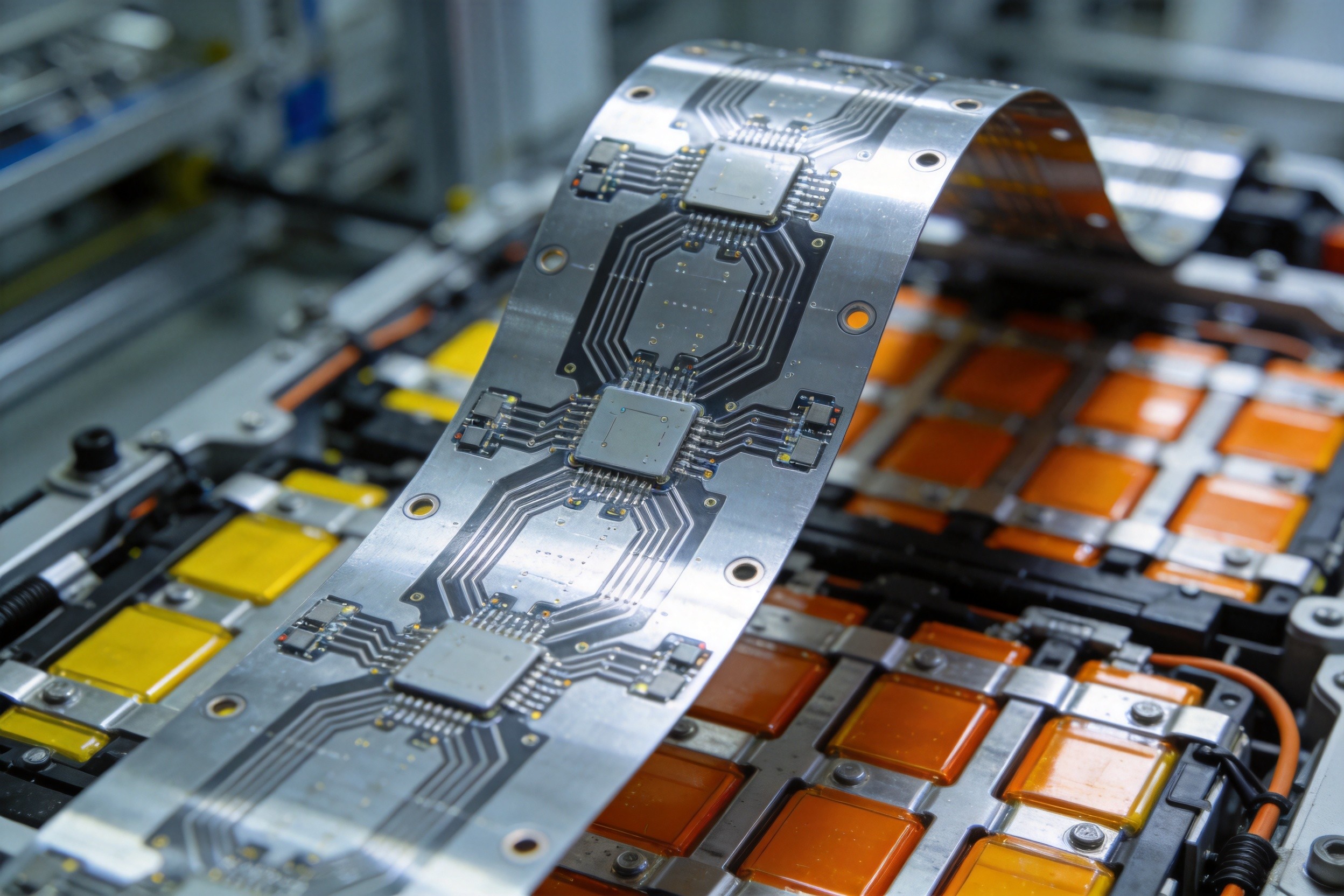
EV battery management system flex PCB with cell monitoring circuits

Case 1: ADAS Domain Controller — Multi-Sensor Fusion PCB

A Level 2+ ADAS domain controller integrates data from 77 GHz radar, LiDAR, and 4K cameras on a single PCB. The board must process multi-gigabit data streams (≥1 Gbps per sensor channel) while maintaining sensor synchronization accuracy within 50 μs.

PCB Design Approach: A hybrid stack-up combining Rogers RO4350B in the RF radar section (achieved insertion loss of 1.2 dB per 5 cm at 77 GHz, versus 3 dB on FR-4) with high-Tg FR-4 (Isola IS410) in the digital processing section. Differential impedance is controlled to 50Ω ±2% for radar lines (0.18 mm trace width, 0.12 mm spacing) and 100Ω ±2% for Ethernet/LiDAR lines. A clock-tree distribution network radiates from the board center, with each clock branch length-matched to within 0.3 mm, achieving sensor synchronization jitter below 35 μs. ANSYS HFSS electromagnetic simulation verified that cross-channel crosstalk remained below −70 dB.

Result: AEB (Automatic Emergency Braking) response latency reduced from 120 ms to 60 ms, with radar detection range restored to 195 m—meeting ISO 22178 safety margins.

Case 2: EV Battery Management System — Flex PCB in Harsh Environments

A BMS for an 800 V lithium-ion battery pack must monitor 108 cell voltages (millivolt accuracy) and temperatures across a physically complex, three-dimensional cell arrangement. Rigid PCBs cannot conform to the cylindrical and pouch cell geometries.

PCB Design Approach: A 4-layer flexible PCB using adhesiveless polyimide substrate (Tg > 300°C, UL 94 V-0) with rolled-annealed copper for dynamic bending reliability. Voltage sensing traces use controlled 50Ω impedance with guard traces. ZIF connectors rated to 125°C provide module-to-module interconnection. Conformal coating protects exposed areas from electrolyte exposure and humidity. The flex circuit withstands 100,000+ dynamic bend cycles at a 6 mm radius per IPC-2223C.

Result: Cell voltage measurement accuracy of ±2 mV across the full −40°C to +125°C operating range, with zero open-circuit failures after 3000 thermal cycles (−40°C to +125°C) per AEC-Q100 Rev H.

Case 3: Powertrain ECU — Thermal Management in the Engine Compartment

An engine-mounted ECU controlling fuel injection and ignition timing must operate continuously at ambient temperatures up to 150°C, with internal power MOSFETs dissipating 150 W during peak load.

PCB Design Approach: A 6-layer board using 2.5 oz (89 μm) inner copper and 3 oz (105 μm) outer copper for current carrying and thermal spreading—reducing temperature rise by 42% versus standard 1 oz copper per IPC-2152. Via-in-pad thermal arrays (0.3 mm minimum diameter, 1.2 mm maximum pitch) under the MOSFET drain pads use copper-filled vias to achieve a junction-to-PCB thermal resistance of ≤1.2 K/W. The board substrate is Isola IS410 (Tg = 180°C), and all solder joints use SAC305+Ni alloy with IMC thickness controlled to 1–3 μm for optimal fatigue resistance.

Result: Junction temperature maintained at 142°C at 150 W dissipation (within the 175°C SiC device safe operating area), with solder joint crack rate below 0.5% after 1500 thermal cycles.


Future Development Trends

AEC-Q100 Rev H and the 10-Year Life Model

The 2025 revision of AEC-Q100 has introduced accelerated life testing models that explicitly target 10-year/200,000-km durability. The thermal cycling requirement has increased to 1500 cycles, and a new combined “vibration + temperature” test simulates the simultaneous mechanical and thermal stresses of real-world driving. ISO 16750-4:2026 has also been updated with cyclic salt-spray testing (240 hours, including humidity–salt-spray–drying cycles) for 800 V high-voltage components in EVs. Timeframe: These requirements are already in effect for new qualifications starting in 2026; existing designs must be re-qualified within 18–24 months.

Centralized Domain and Zonal Architectures

The automotive E/E architecture is transitioning from distributed ECUs (50–100 per vehicle) to centralized domain controllers and zonal architectures (5–10 high-performance computers). This consolidation dramatically increases PCB density, layer count (12–24 layers), and the need for hybrid stack-ups combining RF, high-speed digital, and power sections on a single board. Automotive Ethernet (1000BASE-T1, 10GBASE-T1) and PCIe interfaces are becoming standard on ADAS PCBs, demanding signal integrity expertise comparable to data center design. Timeframe: Domain controllers are in production now; zonal architectures will dominate new vehicle platforms by 2028–2030.

ISO 26262 Third Edition and AI/ML Safety

The forthcoming third edition of ISO 26262 (expected 2027) will address the safety of AI and machine-learning-based systems for the first time, including requirements for training-data integrity, model verification, and runtime monitoring. For PCB design, this implies additional sensor-fusion processing capacity, redundant inference pathways, and hardware-level monitoring of AI accelerator health—further increasing board complexity and reinforcing the need for functional-safety-aware layout practices. Timeframe: Draft provisions are under discussion; formal adoption is expected in 2027 with a 2–3 year transition period for the industry.


Conclusion

Automotive electronics PCB design exists in a regulatory environment where reliability is not aspirational but mandatory. The AEC-Q and ISO 26262 frameworks define quantitative thresholds that every material selection, every via placement, and every solder joint must satisfy. As vehicles evolve toward software-defined, electrically propelled, and autonomously driven platforms, the PCB is no longer a passive interconnect—it is the physical infrastructure of safety. For electronics manufacturers entering the automotive supply chain, compliance is the entry ticket, but engineering excellence—demonstrated through robust thermal design, meticulous impedance control, and verifiable functional safety—is what separates suppliers who thrive from those who are replaced.

Need automotive-qualified PCB manufacturing? Connect with our team to discuss IATF 16949-certified production capabilities and AEC-Q-compliant design support.

Online Inquiry Form

Support Excel, PDF, CSV format files for full BOM list quotation

Submit your component procurement and custom packaging needs via the form below. We will provide a detailed quotation and professional solution within 1–8 working hours.

Service & Packaging

Materialparts is a professional electronic component supplier based in Shenzhen, China, with over 20 years of global trading experience. We integrate component procurement, quality inspection, technical support, customized packaging, and global delivery services to provide one-stop supply chain solutions. Our business covers industrial control, automotive electronics, consumer electronics, medical devices and other industries. We always adhere to genuine sources, stable supply and considerate after-sales service.

Core Services

1. One-stop Sourcing & BOM Support

We specialize in a full range of passive and active electronic components, including SMD resistors, power resistors, connectors, aviation connectors, LED beads, flexible circuit boards, printed circuit boards, and integrated circuits. Our professional team provides BOM list consolidation, component matching, and alternative model recommendation services. We support sample orders, small-batch trial production, and mass production orders with flexible MOQs to meet diverse procurement needs.

2. Genuine Product Guarantee & Full-process Quality Inspection

All products are sourced from official authorized channels and are 100% original genuine parts. Every batch of goods undergoes strict full-process quality inspection before delivery, with complete batch records and traceability documents provided. Our products comply with AEC-Q standards for automotive electronics and high-reliability specifications for medical devices. We eliminate counterfeits, refurbished parts and defective products from the source to secure your project production.

3. Fast Quotation & Order Processing

Our customer service team responds promptly to inquiries and quotation requests. All in-stock orders will be processed within one working day. We provide stocking reservation services for long-term cooperative customers, effectively solving problems such as component shortages and unstable supply chains.

4. Professional Technical Support

Our senior engineer team provides free technical consultation, model selection guidance and original manufacturer datasheets. We assist customers in solving problems related to product R&D, circuit design and component application, providing reliable technical support for project progress.

5. Sourcing for Special Components

Relying on our global supply chain network, we professionally source scarce components, obsolete parts and customized special components to efficiently solve your procurement difficulties.

6. Global Logistics & Document Services

We cooperate with mainstream international logistics providers including DHL, FedEx, UPS and TNT to achieve fast global delivery. We can provide complete export documents such as customs declaration files, commercial invoices and packing lists to ensure smooth customs clearance for international shipments. Local pickup is also available for customers in Shenzhen, China.

Professional Packaging Standards

Electronic components are sensitive to static electricity, collision, moisture and dust. We adopt industry-standard anti-static packaging solutions to fully ensure the integrity of goods during transportation and storage.

1. General Packaging Specifications

  • All components are packed separately to avoid damage caused by friction and collision;
  • Shockproof buffer materials are added for fragile products to ensure transportation safety;
  • Each package is clearly marked with part number, quantity, batch number and specifications for easy inventory counting and management.

2. Classified Professional Packaging

  • Anti-static Packaging: Static-sensitive components such as chips, circuit boards and sensors are packaged with anti-static bags, shielding boxes and conductive foam in strict accordance with international anti-static standards to prevent static damage.
  • Vacuum Moisture-proof Packaging: Moisture-sensitive components are vacuum-sealed with desiccants to isolate humid air, suitable for ocean transportation and long-term storage.
  • Original Factory Packaging: Integrated circuits of brands such as NXP are delivered with original reels, trays or tubes by default, retaining complete original packaging and adapting to automated SMT production lines.
  • Discrete Device Packaging: Discrete devices such as SMD resistors, power resistors and LEDs are quantitatively and classifiedly packaged with accurate quantity and clear marking.
  • Connector / Aviation Connector Packaging: Hard outer packaging is adopted to prevent pin bending and structural deformation.

3. Custom Packaging Services

We provide value-added services including personalized packaging, custom labeling and re-reeling according to customer requirements, fully matching your production and warehouse management standards.

Contact Information

For service consultation or packaging customization, please feel free to contact us:
Email: [email protected]
Tel / WhatsApp: +86 13760382860
Address: Room 2919, Guoli Building, Huaqiang North, Futian District, Shenzhen, Guangdong, China
 
Shipping & Payment

Materialparts is a professional global supplier of electronic components with over 20 years of industry experience. We provide one-stop supply of passive components, integrated circuits, as well as parts for industrial control, automotive electronics, consumer electronics and medical devices. Below are the unified shipping and payment policies applicable to all orders, samples and bulk purchases worldwide.

1. Payment Terms

We offer a variety of secure and convenient payment methods to meet diverse business cooperation needs. Details are as follows:
  1. Accepted Payment Methods
  • T/T (Bank Wire Transfer): The primary settlement method for bulk orders and a widely used international payment channel.
  • PayPal: Ideal for small orders, sample orders and quick payments.
  1. Settlement Currency


    US Dollar (USD) is the default settlement currency. RMB is available for domestic customers.

  2. Bank Charges


    All transfer fees, intermediary bank charges and other remittance-related expenses shall be borne by the buyer.

  3. Payment Requirements
  • Sample and small orders: Shipment will be arranged upon full payment.
  • In-stock bulk orders: Goods will be delivered within 2 to 3 working days after full payment.

2. Shipping & Delivery

We partner with leading global logistics providers to ensure safe and fast delivery worldwide. Relevant details are listed below:
  1. Logistics Partners
  • International Express: DHL, FedEx, UPS, TNT
  • Economy Logistics: Air freight and sea freight for large-volume cargo
  • Domestic Delivery: SF Express, Yunda Express
  1. Order Processing Time
  • In-stock items: Orders confirmed and fully paid before 14:00 (GMT+8) will be shipped on the same day. All other orders will be dispatched within 1 to 2 working days.
  • Out-of-stock or sourced items: The delivery lead time will be confirmed separately according to brand and inventory status.
  1. Estimated Transit Time
  • International Express: 3 – 7 working days globally
  • Air Freight: 7 – 12 working days
  • Sea Freight: 25 – 40 working days for heavy and large bulk cargo
  1. Shipping Fee Rules
  • Shipping cost is calculated based on package weight, volume, destination and delivery method.
  • Both freight prepaid and freight collect are available. Please provide your courier account number in advance if you choose freight collect.
  • Free international express delivery is offered for large orders. Terms for long-term partners can be negotiated separately.
  1. Shipment Tracking
     

    Within 24 hours after dispatch, we will send the tracking number, commercial invoice, packing list and other documents to your email or communication account. You may check the shipment status online in real time.

3. General Order Rules & Notes

  1. MOQ & Sample Service


    We support flexible minimum order quantities for samples, small-batch and large-batch orders. All sample orders shall comply with the above shipping and payment policies.

  2. Packaging Standard


    All electronic components are packed with professional anti-static and shockproof materials. Original factory packaging is available for branded chips and integrated circuits.

4. Customs & Liability Statement

  1. Import Duties & Taxes


    All import duties, customs clearance fees and local taxes incurred for international shipments shall be borne by the buyer. We will provide complete customs documents to assist you with clearance procedures.

  2. Handling of Lost or Damaged Goods
  • In case of loss or severe damage during transit, please contact us within 48 hours after receiving the tracking information. We will assist you in filing a claim with the logistics provider.
  • We shall not be liable for any losses caused by incorrect delivery address, wrong contact information or the buyer’s refusal to complete customs clearance.

5. Local Pickup in Shenzhen

Local pickup service is available for customers in Shenzhen and surrounding areas:
  • Address: Room 2919, Guoli Building, Huaqiang North, Futian District, Shenzhen, Guangdong Province, China
  • Business Hours: 09:00 – 18:00, Monday to Friday. Closed on weekends and official public holidays.
  • Notice: Please make an appointment via email or communication tools one day in advance, and present your order information upon pickup.

Contact Information

Email: [email protected]

Tel / WhatsApp: +86 13760382860

Quality Assurance

Quality is the core foundation of our long-term global cooperation. With over 20 years of experience in the electronic component industry, Materialparts has built a strict and standardized quality management system covering component sourcing, incoming inspection, full-batch testing, packaging and delivery. We are committed to delivering 100% genuine, high-reliability electronic components for industrial control, automotive electronics, consumer electronics and medical device industries, and fully safeguarding your production and R&D projects.

1. Authorized & Genuine Sourcing Promise

All of our electronic components are procured from official authorized distributors and original manufacturers. We strictly reject counterfeits, refurbished parts, disassembled components and gray-market goods. Every product is guaranteed to be brand-new original parts and fully consistent with the original technical parameters. For branded products such as NXP IC series, we maintain complete supply channel documents to realize full product traceability.

2. Strict Full-batch Quality Inspection

We implement 100% full-batch quality control for all goods before shipment. Our professional QC team conducts multi-dimensional tests including appearance inspection, electrical parameter testing, performance verification and packaging check. Each batch of components is attached with complete inspection reports and batch records. We stick to zero-tolerance standards for defective products to ensure every piece of component meets industrial application requirements.

3. Industry Standard Compliance

Our products comply with a variety of international industry quality standards to adapt to high-standard application scenarios:
  • Automotive Electronics: All automotive-grade components pass AEC-Q series certification, featuring excellent stability and durability to adapt to complex vehicle operating environments.
  • Medical Devices: High-reliability components meet medical industry safety and compliance regulations, ensuring stable operation for medical equipment.
  • Industrial Control & Consumer Electronics: Products conform to universal international electronic industry standards, suitable for long-term continuous operation of various equipment.

4. Professional Reliability Control

For static-sensitive, moisture-sensitive and precision components such as ICs, PCBs, sensors and connectors, we carry out reliability screening in advance. Combined with standardized ESD anti-static packaging and vacuum moisture-proof packaging, we avoid component damage caused by static electricity, dampness or collision during storage and transportation, and retain the original performance of products.

5. Traceability Management System

We establish a complete product traceability system. Each batch of goods corresponds to independent batch number, sourcing record, inspection record and delivery record. Customers can query the whole lifecycle information of components at any time. This system effectively solves quality risks and facilitates after-sales handling and production quality control for your company.

6. After-sales Quality Guarantee

If any product is confirmed to have non-conformity quality problems due to our reasons after receipt, we provide free return, exchange and supplementary delivery services. Our professional quality team will also conduct root cause analysis to optimize our quality control process. We respond to quality feedback within 24 hours to resolve your worries efficiently.

Contact Us

If you have inquiries about our quality standards, inspection procedures or product certification documents, please feel free to contact us:


Email: [email protected]
Tel / WhatsApp: +86 13760382860
Address: Room 2919, Guoli Building, Huaqiang North, Futian District, Shenzhen, Guangdong, China