


Product Overview
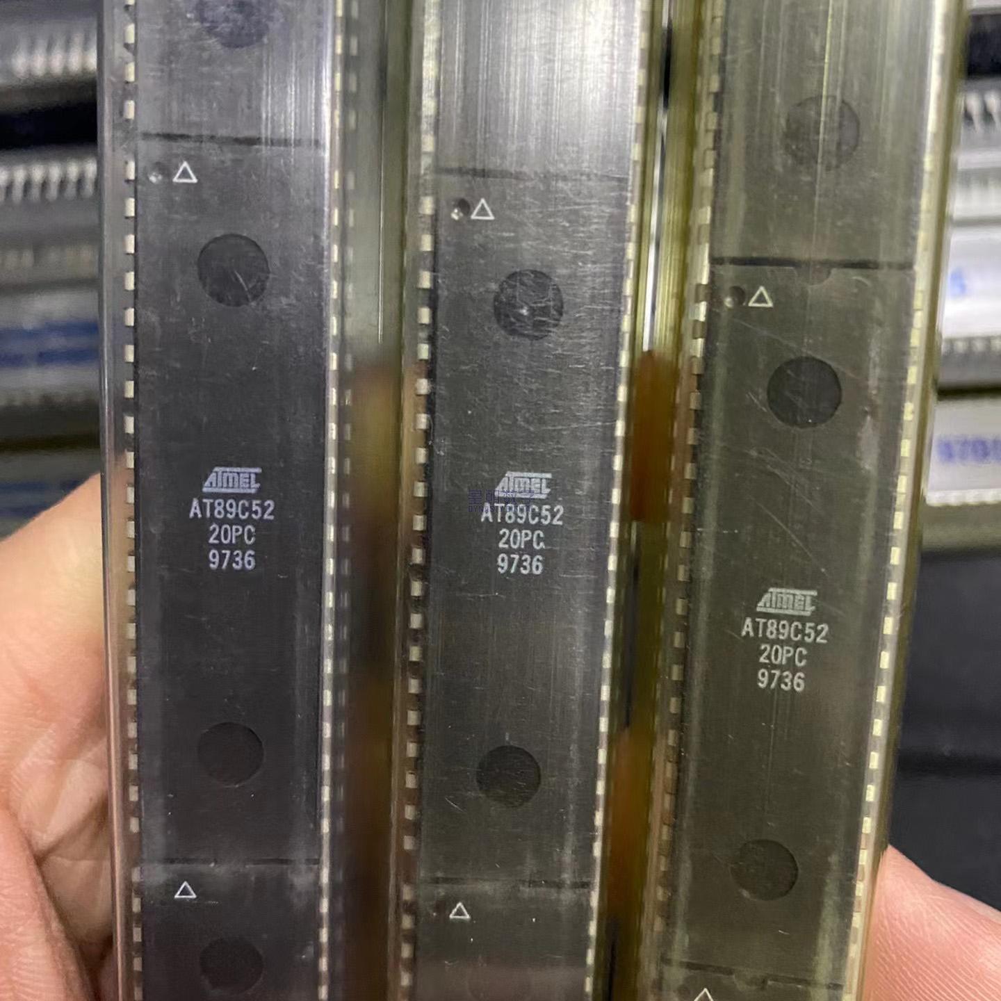
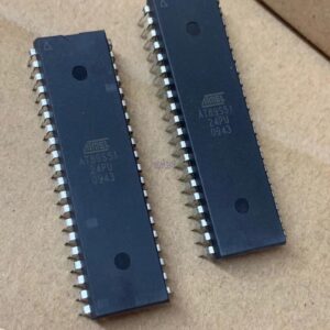
The AT89C52-20PC is a low-power, high-performance CMOS 8-bit microcontroller from Atmel (now Microchip), featuring 8KB of in-system programmable Flash memory and 256 bytes of internal RAM. Based on the industry-standard 80C51 architecture and instruction set, the AT89C52 is fully compatible with MCS-51 products while offering enhanced features and higher integration. The device provides three 16-bit timer/counters (compared to two in the standard 8051), 32 programmable I/O lines, a full-duplex serial UART port, and eight interrupt sources. The on-chip Flash memory can be reprogrammed in-system or via a conventional nonvolatile memory programmer, supporting 1,000 write/erase cycles. Operating at up to 20MHz (this specific -20PC speed grade), the AT89C52 delivers up to 2 MIPS of processing throughput. The device supports low-power idle and power-down modes for battery-powered applications. Packaged in a 40-pin PDIP (Plastic Dual In-line Package) with through-hole mounting, the AT89C52-20PC is widely used in education, prototyping, and cost-sensitive embedded control applications. Note: This device is not recommended for new designs; consider the AT89S52 (with ISP, watchdog timer, and dual data pointer) as a recommended replacement.
Key Specifications
| Parameter | Conditions | Min | Typ | Max | Unit |
| Core Architecture | 8-bit 80C51 (MCS-51 compatible) | ||||
| Operating Voltage (VCC) | 4.0 | 5.0 | 5.5 | V | |
| Clock Frequency | 0 Hz to max | 0 | 20 | MHz | |
| Flash Program Memory | In-System Programmable | 8 KB (8192 bytes) | |||
| Flash Endurance | Write/Erase cycles | 1000 | cycles | ||
| Internal RAM | 256 x 8-bit (256 bytes) | ||||
| External Memory | Code + Data | 64KB each (addressable) | |||
| Program Memory Lock | 3-level lock bits | ||||
| I/O Pins | 4 ports x 8 bits | 32 programmable I/O lines | |||
| Timer/Counter 0 | 16-bit, Mode 0/1/2/3 | 16-bit Timer/Counter | |||
| Timer/Counter 1 | 16-bit, Mode 0/1/2/3 | 16-bit Timer/Counter | |||
| Timer/Counter 2 | 16-bit, with capture | 16-bit Timer/Counter (auto-reload) | |||
| Total Timers | Three 16-bit timer/counters | ||||
| Serial Port (UART) | Full duplex | 1 UART (Mode 0/1/2/3) | |||
| Interrupt Sources | 8 interrupt sources, 2 priority levels | ||||
| Interrupt Vectors | INT0, INT1, T0, T1, Serial, T2 (6 vectors) | ||||
| Oscillator | External crystal / RC oscillator | ||||
| Oscillator Pins | XTAL1, XTAL2 | ||||
| Power Supply Current | Active, 12MHz | 25 | mA | ||
| Idle Mode Current | 6.5 | mA | |||
| Power-down Mode Current | 50 | μA | |||
| Operating Temperature | Commercial (PC suffix) | 0 | +70 | °C | |
| Package | 40-pin PDIP (Plastic Dual In-line Package), through-hole | ||||
| Programming Method | Parallel programmer (12V VPP) | ||||
| ISP Support | No (parallel programming only) | ||||
Features
- Compatible with MCS-51 (8051) instruction set and pinout
- 8KB bytes of In-System Programmable (ISP) Flash memory
- 1,000 write/erase cycle endurance
- 256 x 8-bit internal RAM (double of standard 8051)
- Three-level program memory lock (code protection)
- 32 programmable I/O lines (Port 0, 1, 2, 3)
- Three 16-bit timer/counters (T0, T1, T2)
- Timer 2 with capture and auto-reload modes
- Eight interrupt sources with two priority levels
- Full-duplex programmable serial channel (UART)
- Fully static operation: 0 Hz to 20 MHz
- Low-power Idle and Power-down modes
- On-chip oscillator and clock circuitry
- External memory interface (64KB code + 64KB data)
- Boolean processor (bit manipulation instructions)
- 128 software breakpoints support
- 40-pin PDIP package (through-hole mounting)
- Wide industry adoption and extensive code base
Pin Configuration (PDIP-40)
| Pin No. | Name | Description |
|---|---|---|
| 1 | P1.0 (T2) | Port 1 bit 0 / Timer 2 external input |
| 2 | P1.1 (T2EX) | Port 1 bit 1 / Timer 2 reload/capture |
| 3-8 | P1.2 – P1.7 | Port 1 bits 2-7 (general purpose I/O) |
| 9 | RST | Reset input (active high) |
| 10 | P3.0 (RXD) | Port 3 bit 0 / Serial receive |
| 11 | P3.1 (TXD) | Port 3 bit 1 / Serial transmit |
| 12 | P3.2 (INT0) | Port 3 bit 2 / External interrupt 0 |
| 13 | P3.3 (INT1) | Port 3 bit 3 / External interrupt 1 |
| 14 | P3.4 (T0) | Port 3 bit 4 / Timer 0 input |
| 15 | P3.5 (T1) | Port 3 bit 5 / Timer 1 input |
| 16 | P3.6 (WR) | Port 3 bit 6 / Write strobe (external RAM) |
| 17 | P3.7 (RD) | Port 3 bit 7 / Read strobe (external RAM) |
| 18 | XTAL2 | Oscillator output |
| 19 | XTAL1 | Oscillator input |
| 20 | GND | Ground (0V) |
| 21-28 | P2.0 – P2.7 | Port 2 bits 0-7 (high address byte) |
| 29 | PSEN | Program Store Enable (external code read) |
| 30 | ALE/PROG | Address Latch Enable / Programming pulse |
| 31 | EA/VPP | External Access enable / Programming voltage |
| 32-39 | P0.0 – P0.7 | Port 0 bits 0-7 (low address/data bus, open-drain) |
| 40 | VCC | Supply voltage (+5V) |
Applications
- Embedded control systems
- Industrial automation and control
- Consumer electronics
- Home appliances
- Educational and learning platforms
- Development boards and prototyping
- Motor control and drive circuits
- LED displays and control panels
- Simple communication interfaces
- Security systems
- Toys and games
- Legacy 8051-based system maintenance